Fire hose pressure drop
.jpg)
What is load loss?
It's the difference in pressure between the pipe inlet and outlet. It is expressed in joules (J) per hectometer. Each pipe generates its own pressure drop.
Pressure loss law :
- Directly proportional to plant length (L)
- Directly proportional to the square of the flow rate (Q)
- Inversely proportional to pipe diameter (D)
- Dependent on internal pipe roughness (coef. K) and nature of product conveyed
- Depends on gradient, 1 bar per 10 meters (Z)
Pressure losses due to pipe length :
These losses are determined for a standard length of 100 m (L) at a given flow rate corresponding to the operating flow rate of the various accessories. Since pressure losses are directly related to pipe length, we can deduce the following relationship:


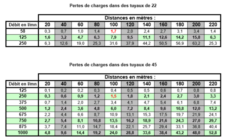
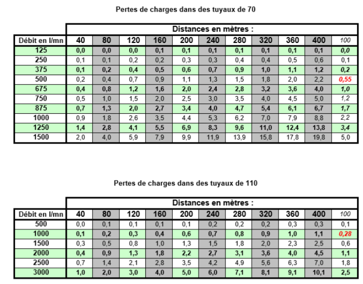
- With Js in bars (for 100m at actual flow rate), this is a standard value given by the manufacturer for a given flow rate (see table at end of page)
- L in m (standard 100 m)
- Jt in bars (total pressure drop for the length of the plant)
- Lt in m (total length of plant)
So the longer the plant, the greater the pressure drop.
Rule of squares for flow :
For a different flow rate in the same pipe, pressure losses will be different.
Pressure losses are proportional to the square of the flow rate:
- If the flow rate is multiplied by 2 (Q2 = Q1 x 2), then pressure losses are multiplied by 2 squared (J2 = J1 x 2 2)
- If the flow rate is multiplied by 3 (Q2 = Q1 x 3), then pressure losses are multiplied by 3 squared (J2 = J1 x 2 2)
- Etc...

- With Js in bars (for 100m at actual flow rate), this is a standard value given by the manufacturer for a given flow rate (see table at end of page)
- L in m (100 m standard)
- Jt in bars (total pressure drop for the length of the plant)
- Lt in m (total length of plant)
So the longer the plant, the greater the pressure drop.
Head loss J1 for flow Q1
Pressure drop J2 for flow Q2
So if you change the flow rate of your LOS out of sequence, you run the risk of distorting the pressure loss calculations and thus modifying the pressures throughout the plant
Pressure losses due to pipe roughness :
The pressure at the nozzle outlet is lower than that at the pump outlet. This is due to the friction of the water against the pipe walls and obstacles in the hydraulic parts.
These are the pressure losses designated by the letter "J" in the formulas, and its unit is the bar per hectometer (b/hm)
This is a standard value given by the manufacturer for a given flow rate (see table at the end of the page). Pressure losses can vary widely from one brand to another, and we'd like to mention two of the best-performing models on the market: the Kraken Exo and the Mega Flow.
They stand out from all competing models thanks to their low pressure drops and service pressures well above French market standards.
Pressure losses due to level difference :
This is due to the difference in level, which can be either positive, if you go up between the water point and the point of attack, or negative, if you go down between the water point and the point of attack.
A 10 m difference in level is assumed to generate a pressure of 1 bar.
So if the installation is downhill, the difference in level will result in a gain in pressure, whereas if the installation is uphill, the difference in level will result in a loss of pressure.
As a general rule, the following formula is used to determine the pressure associated with the difference in level:
Jh = H/10
- Where Jh is the pressure associated with the gradient in bars
- H being the height difference in m
Example:
For a 15 m rise: +1.5 bar
For a 15 m descent: -1.5 bars
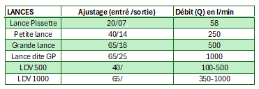
Table of pressures and pressure drops: (see photo)
As the calculations required to find the right discharge pressures at the machine's outlet are becoming more and more complicated in view of the characteristics of lances and the possibility of changing flow rates according to our missions, it is easier to simply apply pre-calculated values according to various establishments. These values are available in the following tables.
Range and reaction of lances :
Span calculation :
-Vertical span = pressure x 5

